Making a Shading Language for my Offline Renderer
As a graphics programmer, I don’t usually spend too much time on something that is not strictly related to computer graphics or game engine. However, I did spend four months in my spare time last year building a shading language for my renderer SORT, which I call Tiny Shading Language (TSL).
In the beginning, I didn’t know how it would end up eventually due to the lack of knowledge about how compilers work in general, this is not something graphics programmers touch regularly. However, it does turn out without too much work, this thing can be done by one person in a few months.
In this blog, I will briefly cover some of my thoughts in designing this shading language library. To be more specific, this blog is about how the system is designed and how it works with an offline CPU renderer, instead of the detailed language implementation.
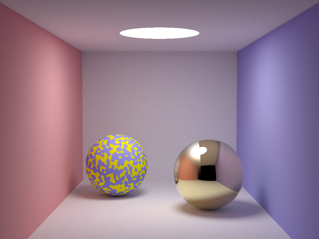
The following is a screenshot of the example tutorial that comes with the TSL library. The patterns on the surface of the two spheres are procedurally generated in TSL.
Motivation
Whenever people heard about my new shading language, the first thing they asked was always, ‘why do you want to make your own shading language since there is already OSL’.
This is a fairly good question, I had the same doubts for more than half a year before putting my hands on it. There are generally several reasons,
- By working on my own shading language, I can learn everything from scratch by myself. This is clearly the biggest reason that I chose to work on it. The knowledge gained in the process of making it would be valuable to my career in the future, at least it should have some indirect impact on my work. It should allow me to have a much deeper understanding of how a programming language compiler works.
- Having my own code base will allow me to change the library anyway I see fit. This alone offers me a lot more flexibility than OSL since I’m not familiar with their implementation.
- Since Apple is currently in the transition from Intel chips to ARM, future MacOSs will be shipped on ARM architecture. Building OSL on ARM will require building all its dependencies on ARM too. If there is any implementation that is x86 specific in any of its dependencies, I will have to find a workaround implementation on ARM too. Without OSL on ARM, there is no way to port my renderer on Apple Silicon. Supporting Apple Silicon is in OSL’s roadmap, but it is unclear when it will be available by the time this blog was written.
- OSL heavily uses this library called Open Image IO, which is another open-source project. While OIIO further depends on several other small libraries like, OpenExr, libpng, libtiff and a few others. Some of the basic data structures are only defined in OIIO, so decoupling OSL with OIIO would require quite some work. This was one of the options that I have considered, but after a second thought, it will also make updating OSL in my renderer very hard since it is locally modified.
- Having too many dependencies does make OSL a bit ‘heavy’ than expected. My original expectation was just to have one OSL lib as dependencies, it certainly didn’t end up the way I planned. Eventually, there are other libs too and on some platforms, some of the libraries have to be dynamically linked too. Ideally, I could have spent much more time to make sure all of the dependencies are statically compiled, but it is way more sophisticated than it sounds. I wouldn’t want to spend too much time building those libraries from source code. Also, some of the pre-compiled libraries are OS-dependent on Ubuntu, which means that I will have to compile it another time on another version of Ubuntu. At the end of the day, after solving all these problems, features in OIIO are not even used in my renderer at all and I do not have a plan to use them in my renderer since doing it from scratch would be lots of fun, it is a dependency purely because OSL needs it.
There are other reasons that motivate me to implement my own shading language. However, those are mostly related to OSL. I would like to avoid having comments about OSL since at the time this blog was written, I was an employee of Sony (Naughty Dog).
With the above-mentioned reasons, I hope I have made it clear why I decided to implement my own shading language. Of course, I am fully aware that my own implementation will be way less robust than OSL since there is a team behind it and this tech has been involved for more than ten years. So my next question after finalizing my decision was whether this is doable by myself in a few months, I definitely didn’t want to deviate from my trail too much, I’m a graphics programmer anyway, no one will expect me to know too many details in designing a compiler.
Taking Advantage of Existed Work
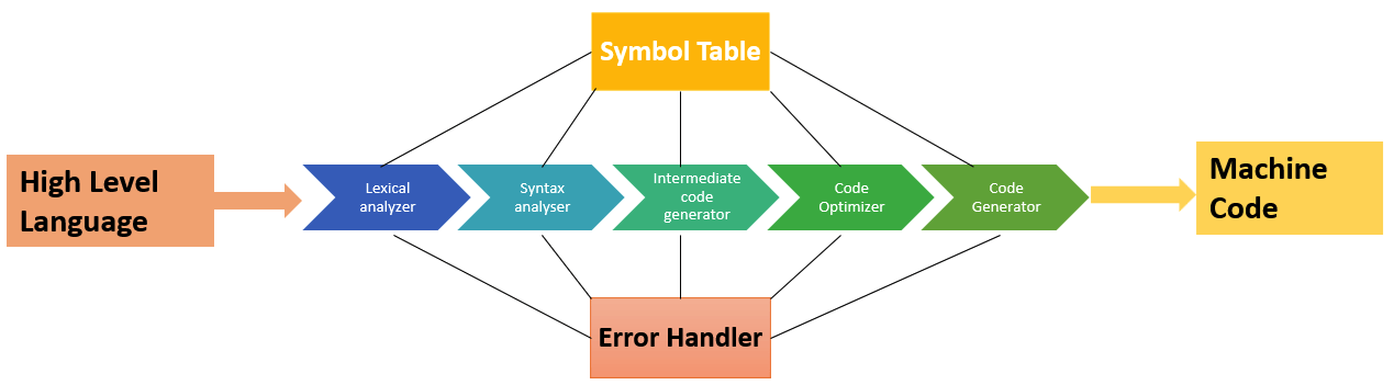
The image below demonstrates some basic stages of compiling a programming language into machine code
Starting from scratch and making everything by myself sounds crazy and it is not likely that I can finish everything in a few months. After some basic research and learning, I found some useful tools that could help me make my shading language a reality.
- Flex
Flex is one of the commonly used tools as a lexical analyzer. Taking a string stream, it will basically tokenize all of the string in a pre-defined manner. - Bison
Bison is a syntax analyzer. It will take tokens generated from Flex and generate an abstract syntax tree. - LLVM
LLVM is short for low level virtual machine. It is a complex infrastructure that could help convert LLVM IR to machine code on different target architectures, like PC, X86, etc. It also does optimization too.
With the these tools, it sounds like I only need to do the following things
- Make a configuration file for Flex to tokenize my shading language.
- Make a configuration file for Bison to use the tokens generated from Flex and generate AST.
- Generate LLVM IR with the AST generated from Bison.
- Compile the IR into JITed machine code with LLVM.
This is way more manageable than writing everything by myself. And it did give me some confidence that this is doable by one person.
However, apart from the basic language support, which is to convert my shading language to JITed machine code, this is far from enough since a programmable shading language for CPU ray tracers is fundamentally different from its GPU counterpart. A large proportion of the project is to design a user-friendly interface and let it fit well in my renderer. This is no less than the amount of work to be done just to convert high level language to machine code.
This blog is mainly about the latter. It won’t mention anything about the former part since there is plenty of resources on the internet that could help in those topics. Kaleidoscope is a very good example that comes with the LLVM library.
Where does It Fit in a Ray Tracer
Before we dive into the details of this shading language, I would like to put down some notes to offer the big picture of how this library fit in a ray tracer so that readers should have a brief idea about how it works with the rest of the system.
A barebone path tracing algorithm could work like this,
- Spawn primary ray for each pixel sample.
- Find the nearest intersection with the scene.
- Use the material information to construct a BSDF.
- Evaluate the BSDF and update the throughput and accumulate it in the result.
- Importance sampling the BSDF and generate secondary rays if needed.
- Get back to step 2 and loop.
The loop stops when there is no intersection found in step 2. Of course, this is also a simplified workflow since there is no volumetric rendering and subsurface scattering in it. But this is more than good enough for me to explain where TSL should fit.
I guess all readers could have guessed at this point. The TSL execution should happen in step 3, which is exactly what the shader language is for. In PBRT 3rd, there are pre-defined materials with hard-coded BSDF and parameters of BXDF are exposed through pbrt input file with limited flexibility. With TSL, a ray tracer can translate shader script during runtime without itself being recompiled and this offers great flexibility. The purpose of TSL shader execution is to reconstruct BRDFs in the target BSDF, this purpose is very similar with what PBRT does with its material implementation, except that it is not hard coded in the ray tracer itself. Shader authoring can happen later when artists are working on assets.
Language System Design
TSL is designed to be simple and easy to use. The syntax of the language is very C-like, just like GLSL, HLSL, OSL. This is user friendly to even new shader authors.
However, a CPU ray tracer shading language has lots of differences that are fundamentally different from a GPU shading language, which has a big impact on its language system design. TSL works in a very simliar manner with OSL, which also works on CPU. The followings are some of the major differences that TSL has compared with a GPU shading language.
-
In a graphics API, before issuing a draw call, we need to send information from host(CPU) to GPU, commonly including constant buffer, vertex buffer, index buffer, etc. Once all of the shader inputs are set, along with other render states, a draw call is issued. Depending on the exact situation, the number of shader executions could be up to a million or even more. In a nutshell, with everything setup once, shaders are usually executed on a massive scale. While TSL’s shader setup and execution is almost always one vs one. This is defined by the nature of CPU ray tracers. CPU’s parallelism is not utilized in the same way as GPU since different threads are not synchronized at all, there is simply nothing like Warp or Wavefront. Without synchronization, since different threads almost never run the same instructions like GPU does, executing shaders multiple times makes almost no sense at all. SIMD optimization would be a fairly bad fit for shaders since there are no four instances of shader executions at the same time.
This is only true in my renderer. OSL has SIMD in its roadmap and some commercial renderers do take advantage of it to run batched shader execution for better performance. -
Modern game engines all support material graph, which is more of a visual programming language tool for technical artists to ‘code’. However, the GPU shader compilers are not aware of such a thing at all. There is something called ‘shader builder’ that builds the finalized shader source code from different shader fragments collected from the material graph. These shaders are usually called material shaders. The other type of shaders in game engines is commonly called in-game shader, which is usually programmed by graphics programers. And the GPU shader compiler will take the shader source code without even knowning whether it is an in-game shader or a composited material shader.
There is generally no ‘in-game’ shader in an offline renderer. But material shader concept is a necessarity to support a wide variety of material appearance on the surfaces. Different from GPU shader compiler, I chose to implement the ‘shader builder’ algorithm inside TSL library just like OSL did so that renderers with TSL integrated only need to take shader fragments, which I call shader unit template, and TSL will be responsible for building the finalized shader code, which the renderer doesn’t even get a chance to see. The benefit of doing this is that renderers are free of the responsibility of implementing a shader builder to support shader-graph-like material. -
In a GPU shader, the inputs are textures, constants and vertics. The output is usually a single plain data structure that has data for the following pipeline stages. The input of TSL is similar to GPU shading language, it has a global constant, global texture handles. While the output and shader source code definition is dramatically different from its GPU counterpart.
It is generally a bad idea to do all BXDF evaluation like game engines do in TSL alone for two reasons.- First, BXDF supports not only its evaluation, but also interfaces for importance sampling. If everything is done in TSL, it means a shader graph must be translated into a few types of shaders, that support evaluation, importance sampling, etc. And whenever it needs more interfaces for BXDF, we need a new type of shader generated in TSL.
- Second, which is equally important, lots of renderers already have solid implementation of quite a few BXDFs. Having everything done in TSL will means for renderers integrating TSL, they need to re-implement everything they did in their BXDF implementation in TSL again. And not to mention there is no stl support in TSL, it will be very hard to implement sophisticated BXDF that could have been easily done in C++.
Due to the above reasons, the output of TSL is designed to be a closure tree just like OSL. A closure basically indicates a BXDF in a renderer. Different from a real-time rendering engines, which mostly use Microfacet and Lambert as its shading model, offline renderers’ material system could be a lot more complex, which is usually defined by a BSDF. A BSDF is composed of multiple BXDFs with them linearly combined. What makes it a bit more complex is that some BRDF takes other BSDF as an input argument, which essentially converts the BSDF to a tree. In TSL, instead of returning a color value, it generates a tree of closures, which matches perfectly well with BSDF’s definition. This will be covered in more detail later in this post. With the introduction of the type of closure tree, the only thing TSL needs to evaluate for real is actually the arguments to reconstruct the BSDF. For example, the base color for a lambert closure.
Here it is worth mentioning that closure concept is just a place holder with its input argument values. It doesn’t necessarily match to BXDF. In the context of volumetric rendering, it can match to medium. As a matter of fact, it can match to anything to be evaluated later. I only used them to evaluate BXDF and medium in my renderer though. -
Unlike most GPU shading languages, TSL does allow call stack. As a matter of fact, TSL eventually will be resolved into CPU executable JITed code, there is simply no reason not to support call stack. Having call stacks will allow shader authors to implement algorithms like traversing a binary tree a lot easier than GPU shaders.
-
Due to the nature of GPU, shader execution is always synchronized across multiple shader cores for better performance. While in a CPU ray tracer, synchronized shader evaluation across multiple threads doesn’t offer too much benefit. TSL will be executed in a synchronized manner in its own thread though. Essentially, executing a TSL shader is nothing but calling a function from the host side, except that the machine code is compiled by TSL, not C++ compiler.
Shader Unit Template
Shader unit template is the very basic compilation unit of TSL shaders. The corresponding concept in OSL is called shader layer. A shader unit template is nothing but a piece of shader code that will be compiled independently.
For example, the following code is an example of shader unit template source code
/*
 * Shader entry for the shader unit template that makes a lamber closure
 */
shader make_closure_lambert( in  color   basecolor,  // input basecolor
                             in  vector  normal,     // intput normal
                             out closure o0          // output closure
                           )
{
    // making a lambert closure with basecolor and its normal
    o0 = make_closure<lambert>( basecolor , normal );
}
This piece of shader code can be compiled into a shader unit template object. It has one output argument, which is a closure that indicates a lambert BRDF. Of course, it is eventually up to my renderer to explain how to interpret this into the final BRDF, which could totally be another type of BRDF too. But commonly, I don’t do it that way.
It is almost a perfect match for a node in a graph-based material system like what Blender offers. Following is an example of a SORT material in Blender,
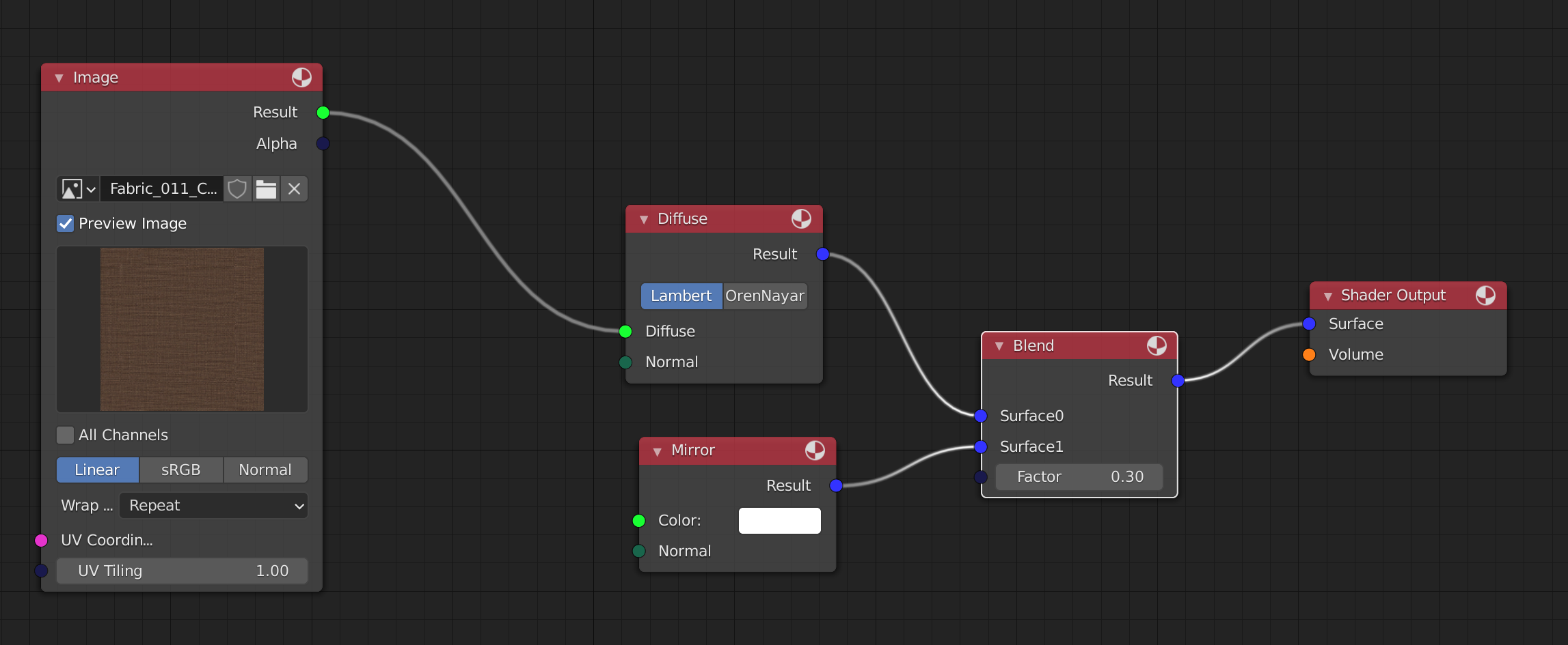
As we can see, the above shader unit template can be used as the representation of the diffuse node in this graph. Both of them take two arguments as inputs and output one argument. Of course, shader unit template doesn’t have to output closure all the time. For example, the image node in the above texture could be defined this way
texture2d g_texture;  // texture handle
shader ImageShaderLinear( vector UVCoordinate ,
                          float  UVTiling ,
                          out color Result ,
                          out float Alpha ,
                          out float Red ,
                          out float Green ,
                          out float Blue ){
    vector scaledUV = UVCoordinate * UVTiling;
    Result = texture2d_sample<g_texture>( scaledUV.x , scaledUV.y );
    Red = Result.x;
    Green = Result.y;
    Blue = Result.z;
    Alpha = texture2d_sample_alpha<g_texture>( scaledUV.x , scaledUV.y );
}
As a matter of fact, this is exactly how this node is defined in my renderer with TSL.
Careful readers might have noticed that we haven’t got a chance to specify the value of some of the input arguments, like the normal in diffuse TSL shader code. And both of the two input arguments are not set with values in the texture sampling TSL code. These will be set during shader group template construction. A benefit of this design is that shader code doesn’t need to be recompiled just because the default value for arguments are different. This means that the upper limit of the number of shader compilation is decided by the number of shader types, which commonly matches the type of material nodes. It is totally independent of the occurrences of each shader node in SORT materials.
Also, there is a global texture handle defined in the above shader. The texture2d_sample<g_texture> code will actually trigger a call back function which eventually delegates things back to renderers. This way, renderers can perform all kinds of complex things like texture filtering, wrapping, or even texture cache system in native C++ programming language instead of TSL.
Shader Group Template
Shader group template is what I used to represent a material with TSL in my renderer. The corresponding concept in OSL is called shader group.
Unlike shader unit template, shader group template doesn’t offer an interface to take any TSL shader code at all. Shader group template commonly takes the following information
- Shader unit templates
- Shader unit template connections
- The default value for arguments in shader unit templates
- Exposed arguments of the shader group templates
// the shader group template that represent the material
auto shader_group = shading_context->begin_shader_group_template("example material");

// add the two shader units in this group
shader_group->add_shader_unit("blend_unit", shader_unit_blend, true);
shader_group->add_shader_unit("diffuse_unit", shader_unit_diffuse);
shader_group->add_shader_unit("mirror_unit", shader_unit_mirror);
shader_group->add_shader_unit("texture_unit", shader_unit_texture);

// setup connections between shader units
shader_group->connect_shader_units("diffuse_unit", "o0", "shader_unit_blend", "in_bxdf0");
shader_group->connect_shader_units("mirror_unit", "o0", "shader_unit_blend", "in_bxdf1");
shader_group->connect_shader_units("texture_unit", "Result", "diffuse_unit", "basecolor");

// Setup the default value for arguments
shader_group->init_shader_input("texture_unit", "UVCoordinate", Tsl_Namespace::make_tsl_global_ref("uvw"));
shader_group->init_shader_input("texture_unit", "UVTiling", 1.0f);
shader_group->init_shader_input("diffuse_unit", "normal", Tsl_Namespace::make_float3(0.0f, 1.0f, 0.0f));
shader_group->init_shader_input("mirror_unit", "normal", Tsl_Namespace::make_float3(0.0f, 1.0f, 0.0f));
shader_group->init_shader_input("mirror_unit", "basecolor", Tsl_Namespace::make_float3(1.0f, 1.0f, 1.0f));

// Expose arguments for the shader group template
shader_group->expose_shader_argument("blend_unit", "out_bxdf");

// indicate to the library the construction of shader group template is done
shading_context->end_shader_group_template(shader_group.get());
Most of the above code is pretty self-explanatory. One detail that deserves our attention is the default value for UVCoordinate argument in texture_unit. Since the above code happens during shader initialization, there is no exact data of texture coordinate at this point at all. TSL allows its users to delay the value setup by referring to a global constant to be set up right before shader execution.
The above code just demonstrates a simple shader graph. In real-world practical examples, there are cases the shader group template could be a lot more sophisticated than the above code. But the general idea holds the same.
TSL Global Constant
It is more than necessary for the host program to provide some input so that shader can be executed with correct information. Such inputs are commonly texture coordinate, vertex position, vertex normal, etc. Basically, it is per shader execution data that can’t be defined during shader authoring or shader compilation. These data will only be available right before shader execution.
To pass the correct information, it is first necessary to define the memory layout of the data structure. And this memory layout needs to be visible to both of TSL shader code and host c++ program. In order to make things easier for TSL users, I made a macro inside TSL library. So to define a global constant, we only need to write down the following code
// Following code needs to appear in a header file
DECLARE_TSLGLOBAL_BEGIN(TslGlobal)
DECLARE_TSLGLOBAL_VAR(Tsl_float3, uvw)          // UV coordinate, W is preserved for now.
DECLARE_TSLGLOBAL_VAR(Tsl_float3, position)     // this is world space position
DECLARE_TSLGLOBAL_END()
// Following code should typically appear in a cpp file
IMPLEMENT_TSLGLOBAL_BEGIN(TslGlobal)
IMPLEMENT_TSLGLOBAL_VAR(Tsl_float3, uvw)          // UV coordinate, W is preserved for now.
IMPLEMENT_TSLGLOBAL_VAR(Tsl_float3, position)     // This is world space position
IMPLEMENT_TSLGLOBAL_END()
The above code will silently create a data structure called TslGlobal and make it visible to both the shader code and its host program. Right before shader execution, this data structure needs to be filled so that shaders can be executed with the correct data.
It is technically possible to have different constant data layout for different shaders. But I didn’t choose to do it to avoid the cost of run-time branching even though modern CPUs might be good at branch prediction.
Shader Instance
Both of shader unit template and shader group template are only templates, they only define things. To execute a TSL shader, a shader instance needs to be constructed from either a shader unit template or a shader group template. It is shader instance that eventually holds the JITed function pointer for the host program to call.
A shader instance is thread-safe in the way that it can be used to execute shader on multiple threads simultaneously with no performance penalty.
Following is a piece of host c++ code demonstrating how to execute a TSL shader
void ExecuteSurfaceShader( Tsl_Namespace::ShaderInstance* shader , BSDF& bsdf ){
    // get the surface intersection data
    const SurfaceInteraction& intersection = bsdf.GetInteraction();

    // fill in the tsl global constant
    TslGlobal global;
    global.uvw = make_float3(intersection.u, intersection.v, 0.0f);
    global.position = make_float3(intersection.position.x, intersection.position.y, intersection.position.z);

    // shader execution
    ClosureTreeNodeBase* closure = nullptr;
    auto raw_function = (void(*)(ClosureTreeNodeBase**, TslGlobal*))shader->get_function();
    raw_function(&closure, &global);

    // parse the surface shader
    ProcessSurfaceClosure(closure, bsdf);
}
Closure
TSL’s closure tree concept is very similar to OSL’s closure tree, if not the same. The introduction of closure tree is probably the biggest difference between TSL and GPU shaders.
Closure is a concept for deferred execution. It is something to be evaluated later, but the real evaluation is left to the renderers, not the shaders. And it should have enough signal for renderers to pick them up. This usually means that closure will have its type id and of course, the arguments constructing the closure, which will be evaluated in TSL shader execution.
As explained before, we won’t evaluate BSDF in TSL. If we don’t evaluate BSDF in TSL, the only choice is to delay the operations of BXDF later to a point where host C++ program can take control. This is somewhat similar to sampling texture in TSL, in which case the real sampling code is still written in C++, not TSL. But it is slightly different since there is no call back function for BSDF operations because these are only needed by the renderer, not the shading language. And most importantly, BSDF reconstruction doesn’t need to be done before TSL shader execution is finished. Closure is pretty much the bridge concept between shader and ray tracer.
Closure Type
Closure is like an indication of BXDF, with specific types and arguments so that it has enough information for renderers to reconstruct the BSDF of its interest. Of course, TSL library itself will have absolutely no knowledge of what type of BXDFs are supported by renderers. It is up to us to register a closure type in renderers before compiling shaders. And renderers need to parse them correspondingly when needed. This can be done this way
To register a closure type, we need to specify a list of arguments first so that we know what information the closure takes. Again, this data structure needs to be visible for both host and target TSL programs. There is a macro in TSL library for us to claim the data structure
// This is the declaration of the data structure of Lambert closure.
// This needs to appear in a header file.
DECLARE_CLOSURE_TYPE_BEGIN(ClosureTypeLambert, "lambert")
DECLARE_CLOSURE_TYPE_VAR(ClosureTypeLambert, Tsl_float3, base_color)
DECLARE_CLOSURE_TYPE_VAR(ClosureTypeLambert, Tsl_float3, normal)
DECLARE_CLOSURE_TYPE_END(ClosureTypeLambert)
// This is the definition of the data structure of Lambert closure
// It has to match what is shown above. This commonly appears in a cpp file.
IMPLEMENT_CLOSURE_TYPE_BEGIN(ClosureTypeLambert)
IMPLEMENT_CLOSURE_TYPE_VAR(ClosureTypeLambert, Tsl_float3, base_color)
IMPLEMENT_CLOSURE_TYPE_VAR(ClosureTypeLambert, Tsl_float3, normal)
IMPLEMENT_CLOSURE_TYPE_END(ClosureTypeLambert)
Once we have the closure type, registering the type in TSL library could be easily done through this code.
// register lambert closure
ClosureTypeLambert::RegisterClosure();
Once it is registered in TSL’s system. TSL shader will recognize the closure type and generate the correct data if it is seen. It is already shown in the first piece of code in this blog
o0 = make_closure<lambert>( basecolor , normal );
As we can see, there are two arguments in this closure type, they are all float3. And the name of the closure type has to match what is specified in the macro.
Closure Operations Supported in TSL
Closure almost behaves a color in TSL, except that it only supports the following operations
- Closure can add with another closure, but not with a regular color in TSL. This does make sense since it makes no sense for a BXDF to blend with a constant color in offline renderers.
- Closure can only multiple with a regular color, closure can’t multiply with another closure. The color is pretty much the weight for the closure, weighting a closure with another closure makes absolutely no sense at all.
- Results of the above two operations will be a closure type, it is not a regular color. So the results of the above operations will have to stick to the above two rules too.
Since closure could be treated as an indication of BXDF, the above rule makes sense. The same rule applies in cases where closure is used for other deferred process, like medium. It is shader authors’ responsibility to make sure no invalid math operations will be performed for closure type in TSL, which will easily result in compilation errors.
Closure Tree
A closure tree is usually what is generated for renderers to parse so that the expected BSDF can be reconstructed through its information. It should have the type of closures with the specific values for each argument.
For example, with the above example, a closure tree could be like this
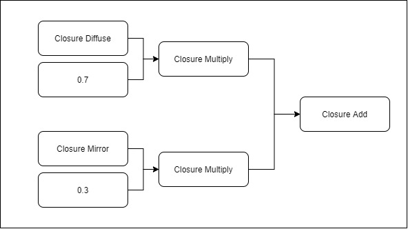
We can clearly notice from the above data structure that non-closure nodes have been resolved in the final closure tree. It is not up to renderers to evaluate the non-closure nodes, TSL should do it. There are two implicit closure types generated
- Closure Add
This simply adds two closure together - Closure Multiply
This indicates that there is a closure with a weight.
With the above data structure, it is easy for any renderers to parse it and generate the BSDF with 70% lambert and 30% mirror in it. And the exact arguments for constructing the BXDF is already packed in the above data structure by TSL. Renderers should have enough information to reconstruct the expected BSDF.
Recursive Closure
One of the advanced closure usages is that a closure can be used as an input argument for another closure. This doesn’t belong to the above two operations mentioned. This is pretty much the only exception.
The following code is borrowed from my renderer SORT, it demonstrates the idea pretty well
// functions defined by c library
float powf( float base , float exp );
float logf( float x );

float helper( float x , float inv ){
    float y = logf(x) * inv;
    return y * y;
}
shader bxdf_coat(   float     IndexofRefraction ,
                    float     Roughness ,
                    color     ColorTint ,
                    closure   Surface ,
                    vector    Normal ,
                    out closure Result ){
    float inv = 1.0 / ( 5.969 - 0.215 * Roughness + 2.532 * powf(Roughness,2.0) - 10.73 * powf(Roughness,3.0) + 5.574 * powf(Roughness,4.0) + 0.245 * powf(Roughness, 5.0) );
    color sigma;
    sigma.r = helper(ColorTint.r,inv);
    sigma.g = helper(ColorTint.g,inv);
    sigma.b = helper(ColorTint.b,inv);
    Result = make_closure<coat>( Surface , Roughness , IndexofRefraction , sigma , Normal );
}
As we can notice from the above code, the first argument of Coat closure is a closure itself, which is passed in. To give readers a better idea of its use case in my renderer, the following is a screenshot of a SORT material

The Coat material node does take one surface node, which essentially just matches to a closure tree, as its arguments. This offers the flexibility of supporting coating any other materials in the renderer. In the above case, a Disney BRDF is coated with this type of material, this gives a nice coating later on top of Disney’s BRDF. Disney BRDF has its own coat layer though, but their BRDF model’s coat layer shares the same normal data, which means that we will lose the smooth coating. Of course, it won’t be too hard to slighly modify Disney BRDF to support multiple layers of normal. But the point here is that recursive closure offers more flexibility.
Following is a screenshot of the final rendered shot, the above material is for the top of the helmet
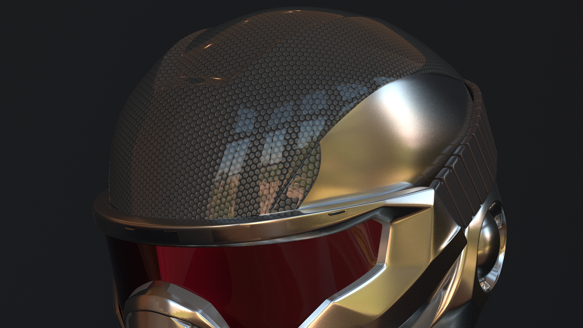
We can easily notice that the coating layer and the underlying layer have a different normal map, which is exactly what we expected as specified in the source material.
Improvement
There aren’t many improvements I made compared with OSL during the development of TSL. Most of the improvements are pretty minor. The only big one is that I made shader group template a type of shader unit template.
Shader Group Template being a Shader Unit Template
This is by far one of my biggest improvements. I had this feature in mind the first day I initiated the project. So in TSL, shader group template is composed of multiple shader unit templates. These shader unit templates are connected so that TSL knows how to generate the target machine code.
Shader group template being shader unit template opens a new door for lots of flexibility. It essentially turns what originally is a tree structure into a multi-dimensional tree structure. Imagine a tree has multiple nodes, each of which could be a tree themselves. A typical use case of this would be TLAS and BLAS in a real-time ray tracing program. This idea applies exactly the same in shader group template. With shader group template being shader unit template, it means that we can add a shader group template in another shader group template. And as a matter of fact, there is no limitation on how many extra dimensions can be added. We can totally have a shader group template A with another shader group template B in it and B can have its own shader group template C in it.
This might not sound like a big feature to expend rendering features. But it does offer lots of value during my asset authoring. Below is a real use case in my renderer
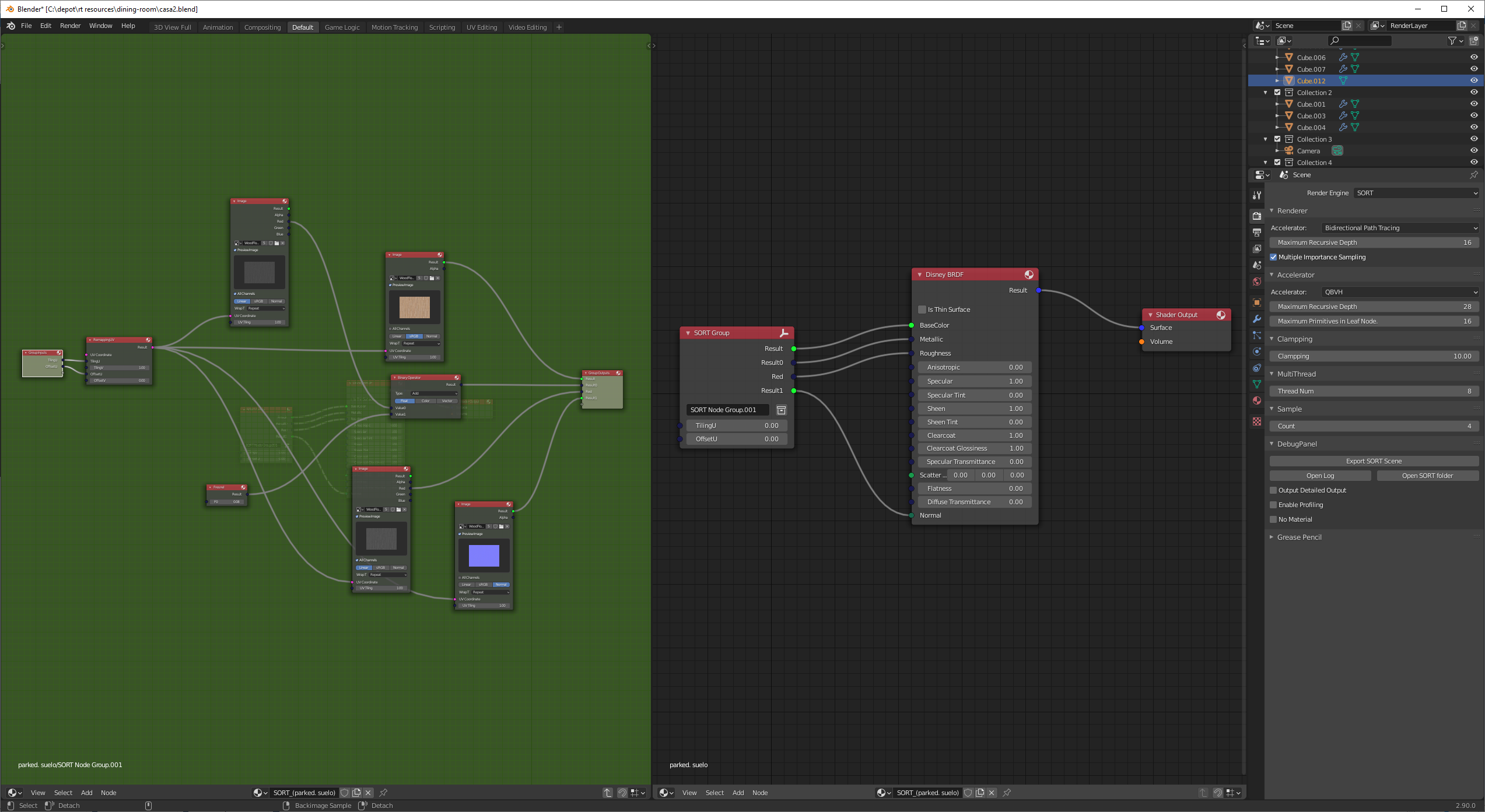
On the right side is the root material graph for a material. We can notice that all of the inputs of the Disney BRDF node comes from a group node, which is defined and shown on the left panel. The group node itself is another shader group template itself, which is embedded in the root shader group template used to represent the material.
The biggest flexibility is that this group node can be used in multiple materials. Any change made in this group material node will automatically propagate to all its client materials.
I did have this feature implemented in my Blender plugin when OSL was used as my shading languages, but there was no clear match for it, I have to hack it in some way that the plugin silently ungroup everything before generating the OSL code. This could be unnecessarily complex if shader group is a shader layer itself. With this feature, it is implemented in a much easier and robust way.
Other Misc Improvements
Apart from the above-mentioned improvement, I also adjust the library in the following way I desired
- Simple Building Process
Building TSL is fairly easy. For detailed steps, please check out TSL’s main page. - Multi-thread Shader Compilation
Both Flex and Bison codes have been adjusted to support multi-thread processing. - Hidden Closure Registration
Closure register is done through an interface, there is no need to have a sperate header file shipped with the final executable. - Shader Unit Template Order
There is no need to pass shader unit templates to shader group template in a specific order, TSL will resolve it for its user. - Light Weight Library
The library is light-weight in a way that no extra dependencies will be needed.
Summary
In this blog post, I put down some notes of my thoughts during the design and implementation of the Tiny-Shading-Language system. The purpose of this blog is to provide readers a big picture of how a toy programmable shading language can be implemented for CPU ray tracers. And it is also for me to keep things recorded somewhere so that I won’t be confused by my implementation when picking this up a few years later.
This article by no means intends to offer a detailed specification of TSL. It only covers the very big picture of it. No detailed interfaces are mentioned. Sadly, I didn’t choose to write a language spec because I have no time to maintain such an expensive thing. For readers who are interested in how it works in a real ray tracer, please check out the example tutorial coming along with TSL library. Of course, it is also suggested to check out my TSL integration in SORT to get a better idea of how this could fit in a slightly more sophisticated ray tracer.
Future Work
With only limited time, TSL is by no means a very stable programmable shading language. There are easily a thousand ways to crash the library without even a warning message by just writing invalid shaders, or even valid ones. Incorrect setup of TSL interface will also potentially crash the system too. However, during my usage of this library in my own renderer, once the shaders are written, it rarely crashes inside TSL shaders.
If I have time, I would like to improve the following things
- More robust language syntax support
- More explanatory error and warning output
- Python interface to parse metadata of a shader unit template
Unfortunately, I have shifted my focus on real-time rendering in my spare time a while ago. I still hope I may have time to pick it up sometime later.
References
[1] LLVM for Open Shading Language
[2] Phases of Compiler with Example
[3] I wrote a programming language. Here’s how you can, too
[4] Writing Your Own Toy Compiler Using Flex, Bison and LLVM
[5] FLEX AND BISON IN C++
[6] How to create an abstract syntax tree while parsing an input stream
[7] Writing a simple Compiler on my own - Abstract Syntax Tree Principle [C][Flex][Bison]
[8] Writing a simple Compiler on my own - Combine Flex and Bison
[9] Make a reentrant parser with Flex and Bison
[10] A Minimal LLVM JIT example for LLVM-5
[11] Open Shading Language Community Meeting