Tessellation on DX11
One of the most important changes that DX11 has made is the brand new feature called tessellation. By introducing three more stages, graphics programmer can tessellate their triangles on the fly. There are some benefits:
- Models with more geometry detail. With phong tessellation, it smoothes the silhouette so that no sharp edge corner will be visible. Combined with displacement map, tessellation can produce bump surfaces in a much more realistic way than what can be achieved with normal map or POM.
- Less calculation on full detailed model. It saves a lot of time by placing intense computation, like bone matrix multiplication, in vertex shader which only processes control points of the model.
- Dynamic LOD. Since tessellation factors, which determines how to tessellate the object, are calculated on the fly during rendering, level of detail can be decided based on factors like distance, angle, etc.
In this article, I’d like to mention some detail that I learned about tessellation.
Introduction
What is tessellation? This should be a question to be addressed first before everything.
Tessellation is a new feature that enables graphics programmer to tessellate their triangles on the fly so that the geometry detail will be enriched. There are three stages right after vertex shader, hull shader, tessellator and domain shader with each stage performing separate functionality.
There are two different functions in Hull Shader, one is the hull shader itself and the other is the constant function which runs on a per-patch basis. In OpenGL 4, it is called tessellation control shader and there is no extra per-patch constant function. Anyway, they are still pretty similar to each other. And they both take in control points and generate some tessellation factors and per-patch constant data.
Tessellator is a fixed function stage. It can’t be programmed directly and neither can it be setup through API interfaces, it is affected by tessellation factors, the output of hull shader (or TCS in OpenGL). It generates those tessellated triangles under the hood and feeds them with the constant data to the next stage, domain shader. One thing to be noted is that the vertices generated in tessellator are located in barycentric coordinate. It is programmer’s job to evaluate the final clip space position with the intermediate data in the barycentric coordinate.
Domain shader is the place for calculating the positions of generated vertices. Whether it is phong tessellation, PN or flat tessellation is decided here. And it is also responsible for generating vertices in clip space, like VS does without tessellation enabled. Of course it can just pass the vertices to the next stage if this is what is needed.
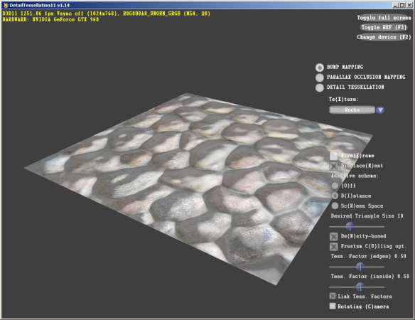
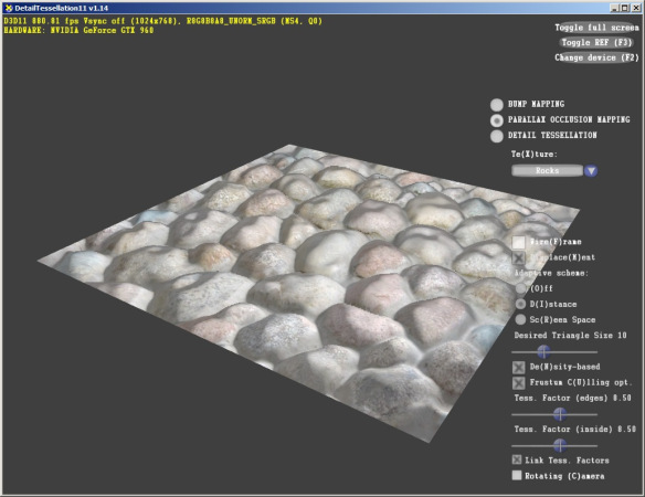
Here is a comparison between tessellation, POM and normal map, those captures come from the detail tessellation demo from D3D SDK. The left one is normal map, the quality quickly breaks down when viewed at a wide angle. POM solves the problem with a ray marching method, however it still shows artifacts at the silhouette of objects. SPOM can solve the problem, however it is far beyond the topic of this blog. Tessellation gives the perfect result, the rocks look really bumpy here.

More Detail
Before diving into the details, let’s see how to enable tessellation through the API. There is no specific functions to enable tessellation. To enable it, you need to create a valid hull shader and domain shader. By binding those shaders in the context, tessellation will be enabled. Of course it is necessary to adjust your shader code in VS. Without tessellation, vertex shader normally outputs at least clip space position. With tessellation, VS can choose only to pass the data to hull shader most of the time.
Besides, the primitive topology needs to be changed accordingly. If you use a low level of detail modal as control point set, it should be “D3D11_PRIMITIVE_TOPOLOGY_3_CONTROL_POINT_PATCHLIST”. Another typical scene is to use “D3D11_PRIMITIVE_TOPOLOGY_POINTLIST” for landscape rendering, each point will be tessellated to a quad after tessellator. Anyway, as long as the information fits your algorithm, any type of primitive topology is fine.
Hull Shader
Let’s talk about hull shader then. A hull shader is the first of the three new stages to implement tessellation. There are two functions, constant function and hull shader.
A constant function runs on a per-batch basis, it outputs some constant data for tessellator and domain shader. “SV_TessFactor” and “SV_InsideTessFactor” are needed by tessellator. And each different type of primitive may need different number of these factors. For example, there should be one inner tess-factor and three outer tess-factors in the constant data. A constant function is also free to generate more data, tessellator will ignore them, however they could be consumed by domain shader. Here is a simple constant function that tessellates all of the triangles:
#define MAX_POINTS 32

// Control point, this is generated from VS
struct VS_CONTROL_POINT_OUTPUT
{
    float3 vPosition : WORLDPOS;
    float2 vUV       : TEXCOORD0;
    float3 vTangent  : TANGENT;
};

// Hull shader output
struct HS_CONSTANT_DATA_OUTPUT
{
    float Edges[3] : SV_TessFactor;
    float Inside : SV_InsideTessFactor;
};

// Hull shader Entry
HS_CONSTANT_DATA_OUTPUT ConstantHS( InputPatch<VS_CONTROL_POINT_OUTPUT, MAX_POINTS> ip,
                                    uint i : SV_OutputControlPointID,
                                    uint PatchID : SV_PrimitiveID )
{
    HS_CONSTANT_DATA_OUTPUT output  = (HS_CONSTANT_DATA_OUTPUT)0;

    // In this simple example, density is purely a constant, but it could be anything
    // calculated from the input data.
	float density = 64.0f;
	output.Edges[0] = density;
	output.Edges[1] = density;
	output.Edges[2] = density;
	output.Inside = density;
    return output;
}
In a real scenario, you may want to adjust your tessellation factor based on information that is already available. Dynamic LOD could be done here through calculating the tessellation factors based on distance between eye point and patch. Apart from all, one can also set up 0 as a factor, it is a valid number for tessellation factor. And tessellator will automatically drop the patch with a zero tessellation factor. Since SV_POSITION is not determined yet, it is impossible for the hardware to do clipping. However it is totally valid to do some culling in this function. If you are certain that the patch won’t be visible at all, you can set 0 as its tessellation factor to prevent it from further processing. Just be very careful when trying hull culling, because it may reject patches that could be visible after displacement.
A Hull shader is the per-control point function. Sometimes, it just passes the data through. Here is some piece of code of a hull shader:
struct HS_OUTPUT{
    float3 vPosition : WORLDPOS;
    float2 vUV       : TEXCOORD0;
    float3 vTangent  : TANGENT;
};

[domain("tri")]
[partitioning("pow2")]
[outputtopology("triangle_cw")]
[outputcontrolpoints(3)]
[patchconstantfunc("ConstantsHS")]
[maxtessfactor(64.0)]
HS_CONTROL_POINT_OUTPUT HS( InputPatch<VS_CONTROL_POINT_OUTPUT, MAX_POINTS> ip,
                            uint i : SV_OutputControlPointID,
                            uint PatchID : SV_PrimitiveID)
{
    HS_CONTROL_POINT_OUTPUT output = (HS_CONTROL_POINT_OUTPUT)0;

    // Copy inputs to outputs
    output.vPosition = inputPatch[uCPID].vPosition;
    output.vUV = inputPatch[uCPID].vUV;
    output.vTangent = inputPatch[uCPID].vUV;

    return output;
}
Different from the constant function or other c functions, there are some parameters setup before the functions. Most of them are self-explanatory. Refer to here if you are confused by any of them. In Unreal Engine 4, more information will be generated in hull shader instead of just passing through the original data. Some of information will be used to fix some crack issues introduced in tessellation. Other information will be used to generate curved surface from control points.
Tessellator
There is not much to say about tessellator since it is non-programmable. However understanding the exact way of tessellating primitives will help even if you are not in control of every thing.
A triangle is taken as an example here. Other primitives like quad behave in a similar way. There are five steps:
- The three edges are tessellated first.
- The triangle is divided into concentric triangles according to the inner tessellation factor.
- The connection between the largest inner triangle and the original one is dropped.
- The outer edges are then subdivided according to the three outer tessellation factor.
- The outer ring is filled with triangles by connecting the points from step 2 with the points from step 4.
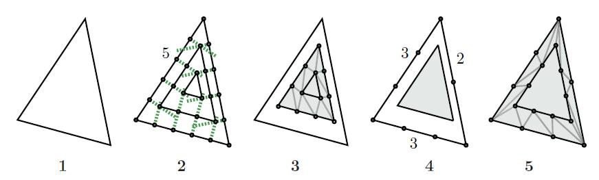
The graph is taken from “An Introduction to Tessellation Shaders” in OpenGL Insights. For this very case, the outer tessellation factors are 3,3,2, and the inner one is 5.
Another detail deserves our attention is how to divide a specific edge given a tess-factor.
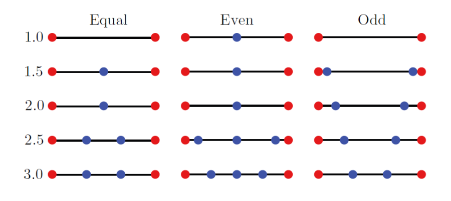
The above graph reveals some detail here. I am not gonna dig into it because it is not mentioned in DX SDK doc and may be different on different platforms. However one important thing to be noticed here is that we have a sudden change as tess factor goes from 2.0 to 2.5 in the first column. “Equal”, “Even” and “Odd” are actually the partitioning parameter setup in hull shader. With “equal” as partitioning method, you may have a sudden change even if you tess factor changes smoothly, that means you may have a similar sudden change in the shape of the geometry. In order to avoid it, choose the other two if possible.
Domain Shader
Domain shader is like another vertex shader. However they are not exactly the same. Here are some differences:
- Domain Shader is right behind tessellator.
- There will be per-patch constant data available, while only vertex data is available in VS unless you pass it through constant data.
- The vertices taking in are located in barycentric coordinate. You have to interpolate all attributes in a way you desire.
The other should be similiar. If GS is disabled, either VS or DS needs to output clip space position. If you want to implement your tessellation with displacement map, here is the place to go. You can read a texture here and adjust the height of the vertex according to some value, which is usually displacement in displacement map.
The way position attributes are interpolated matters here. It defines what kind of tessellation you are using, whether it is flat tessellation, phone tessellation and pn tessellation. Cry Engine 3 provides all three methods by default. Unreal Engine 4 has flat tessellation and pn tessellation. Of course if you want a phone tessellation in UE4, it is quite easy to implement one.
Flat tessellation
As it implies by its name, flat tessellation just interpolate position values linearly, which will be totally flat. It doesn’t make much sense to use the method alone. Usually it is combined with displacement map to create a bumpy surface.
PN tessellation
PN tessellation treats the control points as bezier control points of a curved surface. Different from flat tessellation, PN tessellation will change the shape of the silhouette even if there is no displacement map attached. Its goal is to smooth the silhouette of objects to avoid edge corners. For a further detailed explanation, please check it here. And since UE4 is open-sourced, you can also get its implementation from github.
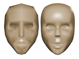
As we can see from the above image, the silhouette will be smoother with PN tessellation.
Phong tessellation
Targeting the same goal with PN triangle, phong tessellation requires less computation to generate similar effects. Here are the steps for phong tessellation:
- Generate tangent plane for each vertex in the triangle.
- Interpolate the position values linearly.
- Project the interpolated vertex position to three tangent planes, you will have three new projected vertices.
- Interpolate the three vertices again to get the final position.
Issues
Tessellation also has some issues if not done well. A well known one is the crack issue. A crack is born if vertices that share the same world position have different attribute which have some influence on the final position. The general rule to fix these issues is to unify all attributes that matter.
Here are some common issues:
- Cracks in PN/Phong tessellation hard edges. By hard edge, it means that an edge is shared by two connected triangle, each has a different geometric normal. Both of PN and Phong tessellation will depend on geometric normal to smooth the surface. Differences between normals will cause displacement along different directions, a crack is born here.
- Cracks can also be caused by texture coordinate difference. Under the circumstance that displacement map is used, texture coordinate is a factor for displacement. If two vertices sharing the same world position have different texture coordinate, there will be cracks.
Generally, those cracks could be eliminated by well defined 3d model. However that puts too much burden on artists. A more practical way of doing this is to fix it through some dedicated algorithm.
There are several algorithms available. Here are some by NVIDIA. Some of them tried to unify the attributes during pre-processing, like Dominate Data Algorithm. Others aims at generating unified attributes on the run, such as AEN(Average Edge Normal).
Conclusion
Tessellation is a brand new feature available on DX11. It offers developers a whole new way to deliver geometry detail to gamers. It is already widely used in PC games, like Metro 2033. Both of Unreal Engine and Cry Engine have internal integration of tessellation. And it is already well supported on quite a few games in the market.
Referencess
[1] OpenGL Insight. http://openglinsights.com/
[2] PN triangle tessellation. http://ogldev.atspace.co.uk/www/tutorial31/tutorial31.html
[3] Microsoft DirectX SDK. https://www.microsoft.com/en-us/download/details.aspx?id=6812