Glass Material Simulated by Microfacet BXDF
Microfacet model can not only be used for rough metal, it can also be used to simulate rough glass material. This blog is about rendering glass material with microfacet model. Basically all of the theory comes from this paper. Different from the pure refraction model mentioned in my previous blog, the bxdf mentioned here can also refract a single incident ray into multiple directions instead of just one.

The above image is generated with my renderer. Each pixel takes 1024 samples and it took me an hour to finish it. As we can see from this image, this bxdf model handles both reflection and refraction. The roughness parameter for both of the objects is 0.04, which makes them look quite similar to combination of pure reflection and refraction bxdf.
Snell’s Law for Refraction Direction
Comparing with reflecting an incident direction along a specific normal, refracting it is much more complicated. I won’t mention anything about derivation of this Snell’s law, it is more of physics than computer graphics. However an important concept that we should know is index of refraction, IOR in short, it defines how light, or any other radiation, propagates through a specific medium. In physics, it affects the speed of light and the wavelength of light. Each media may have different IOR, some of the common ones are listed below:
| Volume Type | IOR |
|---|---|
| Vacuum | 1.0 |
| Air | 1.000293 |
| Water | 1.333 |
| Ice | 1.52 |
| Flint | 1.62 |
| Diamond | 2.42 |
The direct reason that we care about this IOR is because it redirects incident ray through the surface between mediums with different IOR. And the way incident ray is refracted obeys this law:
$$ \dfrac{sin\theta_1}{sin\theta_2} = \dfrac{n_2}{n_1} $$$ \theta $ is the angle between ray and the normal, n is the corresponding IOR. Some basic math shows the equation for computing refracted direction goes this way:
$$ V_r = -\dfrac{n_i}{n_o}V_i + N( \dfrac{n_i}{n_o} (V_iN) - \sqrt{1-\dfrac{{n_i}^2}{{n_o}^2}(1-(V_iN)^2) } ) $$N must be in the same hemisphere with incident ray in this equation. $ 1-\dfrac{{n_i}^2}{{n_o}^2}(1-(V*N)^2) $ can also be negative for certain cases, it happens when light propagates from a medium with higher IOR to a another medium with lower IOR and the incident angle is larger than a threshold, which we call critical angle. And critical angle can be calculated this way:
$$ \theta_{critical} = arcsin( \dfrac{n_o}{n_i} ) $$Handling total internal reflection is crucially important to achieve good result because otherwise some rays will be terminated inside the medium.
Combine Refraction with Reflection
Only handling refraction will never deliver convinced result because there is no such a thing that only refracts light and totally ignores reflected light, at least most stuff in our daily life don’t. The image below is a comparison between those two, as we can notice from it, there is no reflection of area light at the surface of the left objects and some of the light is totally consumed by them. Those are the results caused by totally ignoring reflection during bxdf evaluation.
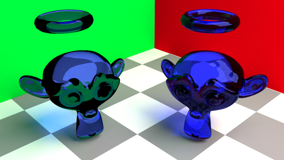
In order to achieve better result like the right ones, it is necessary to evaluate both reflection and refraction. Regarding the rendering equation:
$$ L_{o}(\omega_{o}) = L_e(\omega_i) + \int_{\Omega} L_{i}(\omega_{i}) *f( \omega_{i}, \omega_{o} ) *cos(\theta_{i}) d\omega_{i}$$For certain surfaces, actually most of the time, $ \Omega $ means the hemisphere that the normal points to. However for semi-transparent surfaces, $ \Omega $ is the whole sphere instead of half one. One importance policy during this bxdf evaluation is how to generate rays around the whole sphere.
Let’s start from the simple one by assuming the material is pure-refracted. That said incident ray will only be refracted along one single direction and of course there will also be one single reflected ray, everything stays sharp. And we’ve already knew how to generate reflected ray and refracted ray with given IORs. Since fresnel term decides how much flux is reflected, it makes sense to use this value to decide when to sample reflected or refracted ray.
Pure reflection and refraction bxdf are listed here:
$$ f(\omega_{i}, \omega_{o} ) = \dfrac{F_r(T(\omega_o),\omega_o) \delta( \omega_i - R(\omega_o) )}{|cos(\theta_{i})|} $$ $$ f(\omega_i , \omega_o) = ( 1 - F_r(\omega_i,\omega_o) ) \dfrac{{\eta_o}^2}{{\eta_i}^2}\dfrac{\delta( \omega_i - T(\omega_o) )}{|cos(\theta_{i})|} $$Btdf for pure refraction is the same with previous blog post. However a subtle difference for pure reflection brdf definitely deserves our attention, it is the transmittance direction, instead of reflected direction, that we use to evaluate fresnel term. In special case, which total inner reflection happens, fresnel term should be exactly one. Although it makes sense, I’ve no much idea how to prove these with mathematics, however that’s how other renderers do it. And I’m gonna stick to their solution.
Microfacet for Rough Glass Material
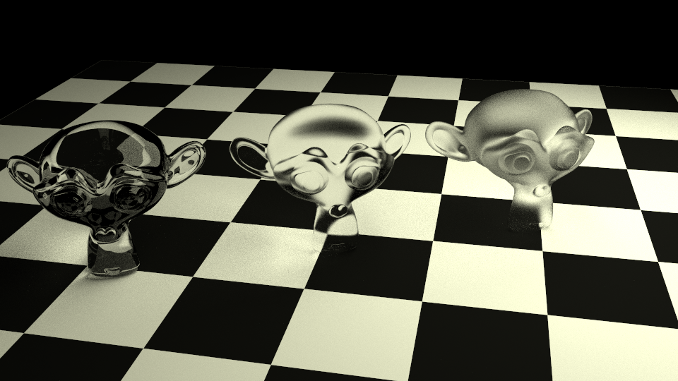
Microfacet model is usually used for simulating metal surfaces in realtime rendering. It assumes the macro surface composes many small micro flat surfaces, each one uses perfect mirror reflection bxdf. With a simple change in this assumption that micro surfaces are not perfect mirror reflection surfaces but perfect transmittance surfaces, the same theory can be used to simulate rough glass. Here is an image with three monkeys, each with a different value of roughness.
The bxdf is the sum of microfacet reflection brdf and refraction btdf:
$$ f( \omega_o, \omega_i ) = f_r( \omega_o , \omega_i ) + f_t( \omega_o , \omega_i ) $$Microfacet brdf is mentioned before:
$$ f(\omega_i,\omega_o,x) = \dfrac{F(\omega_i , h) G(\omega_i,\omega_o,h) D(h)}{4 cos(\theta_i) cos(\theta_o)}$$Microfacet btdf is a little more complex:
$$ f(\omega_i,\omega_o,x) = \dfrac{|\omega_i \cdot h| |\omega_o \cdot h|}{|\omega_i \cdot n| | \omega_o \cdot n| }\dfrac{ {\eta_o}^2 ( 1 - F(\omega_i , h) ) G(\omega_i,\omega_o,h) D(h)}{{(\eta_i (\omega_i \cdot h) + \eta_o (\omega_o \cdot h))^2 }}$$Another big difference for transmittance ray is that $ \dfrac{\omega_h}{\omega_o} $ is different.
$$ |\dfrac{\omega_h}{\omega_o}| = \dfrac{{\eta_o}^2 | \omega_o \cdot h |}{(\eta_i (\omega_i \cdot h) + \eta_o (\omega_o \cdot h))^2}$$Sampling refracted ray direction is similar to the method method here. First a normal needs to be sampled respecting to a given pdf and then choose between reflected and refracted direction by fresnel term, finally evaluate the corresponding bxdf with the generated ray.
References
[1] Microfacet Models for Refraction through Rough Surfaces
[2] Snell’s Law