The Missing Primary Ray PDF in Path Tracing
I was always wondering why don’t we take the PDF of primary ray into account in a path tracer. Sadly there aren’t many resources available explaining it. I guess the book Physically based rendering 3rd will provide some explanation, however it is not released yet. After some searching on the internet, I finally got something to explain it. It actually gets cancelled with the terms in importance function and LTE. It gets cancelled in a very elegant way that we don’t need to put any resources on it at all, which is why many open-source ray tracer don’t consider it in the first place. In this blog, I’m gonna explain the detailed math behind the whole theory.
Primary Ray PDF
First thing first, what is the pdf of primary ray. Assuming we have an imaginary image plane placing at a specific distance from the camera point so that area of each pixel in this image plane is exactly one. Since we already know the resolution of the image, we can calculate the distance with the following equation:
$$ d = \dfrac{res_h}{tan(fov_y)} $$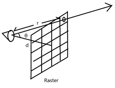
Here is a ray generating through a pixel, we can also get the distance from the eye point and the intersection between the ray and the target pixel.
$$ r = \dfrac{d}{cos\theta} $$Since the area of the pixel is exactly one, the pdf w.r.t area of sampling a point on the pixel is also one. So the pdf w.r.t solid angle of sampling that point from eye point is:
$$ pdf_w = \dfrac{r^2}{cos\theta} $$Putting them all together, you will get the following equation:
$$ pdf_w = (\dfrac{res_h}{tan(fov_y)})^2 \dfrac{1}{cos^3 \theta} $$The $ (\dfrac{res_h}{tan(fov_y)})^2 $ won’t change if image resolution is a fixed number, which is very common most of the time.
Besides the pdf w.r.t solid angle, we also need to pick a single point on the virtual aperture for simulating depth of field effect. The pdf w.r.t area of sampling this point is very simple, just the inverse of the aperture area.
$$ pdf_a = \dfrac{1}{area_{aperture}} $$Measurement Equation
The second thing we need to be clear with is what is stored in a pixel. In a very naive ray tracer, it is usually the generated radiance. However it is much more complex if we consider more. Here is a precise equation showing pixel information:
$$ I = \int_{A_{pixel}}\int_A W_e(p_0\rightarrow p_1)L(p_1\rightarrow p_0) G( p_0 \longleftrightarrow p_1 ) dA(p_0) dA(p_1) $$I won’t show derivation of the equation since it is well out of the scope of this post, I suggest the book Physically based rendering 2rd for further detail on it. However in this book, ‘We’ is assumed to be a dirac delta function, which is actually not. And we are focusing on things before the first intersection, so there is no need to expend the radiance term, we’ll just assume that it is already known. How to get the radiance value correctly is already mentioned in my previous post.
Understanding this equation is very important for implementing something like path tracing and light tracing, especially when DOF is also considered. We’ve already been familiar with the radiance, G term and primary ray pdf, figuring out what ‘We’ is is all left to do.
Importance Function
The ‘We’ term is also called importance function. Unfortunately, I’m not 100% sure that my derivation is a correct one. Since it works pretty well in my renderer, so I decided to go with it until I get a better understanding on it from somewhere else.
First thing we should know about this importance function is that it has illumination fall off by a factor of $ cos^4 \theta $, where $ \theta $ is the angle between the primary ray and the camera forward direction. This thing usually manifest itself as Vignetting, where the corner of the image is a little bit darker than the center.

Here is a demonstration, as we can notice from the image, pixels at corners appear much more dimmer than the center ones. For a better explanation of this fall off thing, I found it kind of helpful.
And in order to avoid the vignetting effect in our offline rendering, we can change the importance function, making it proportional the inverse of this $ cos^4 \theta$ so that we can cancel it in the first place.
Besides this, we also need to consider sampling a point on the virtual aperture. The larger the aperture is, the more DOF effect we will get. In a real world scene, the larger your aperture is, the more light will feed your image sensor. For example, if you aperture is 4 times larger than before, you will have 4 times flux at your image sensor. Image will be 4 times brighter if nothing is done. Usually we need to reduce the shuttering window to 25% so that the total flux at the image sensor is roughly the same, producing images with similar average brightness. When we are doing offline rendering, we are actually capturing an image at a single time point instead of a window. So we are gonna have to put the reduction at somewhere else, that is the importance function we are talking about. That said, if your aperture is 4 times larger, importance function should be 4 times smaller so that we can get results with roughly the same amount of light.
$$ W_e=\dfrac{c}{area_{aperture} cos^4\theta} $$With the above equation, we need to figure out what c is. Let’s hold it for a while, we’ll just assume it is a constant so far.
Monte Carlo Evaluation
With Monte Carlo method, we can get the value of importance function mentioned above this way:
$$ \begin{array}{lcl}I&=&\dfrac{W_e(p_0\rightarrow p_1)L(p_1\rightarrow p_0)G(p_0\longleftrightarrow p_1)}{P_a(p_0)P_a(p_1)} \\\\ &=& \dfrac{W_e(p_0\rightarrow p_1)L(p_1\rightarrow p_0)cos\theta_0}{P_a(p_0)P_w(p_0\rightarrow p_1)} \\\\ &=& \dfrac{c * tan^2(fov_y)}{res_h^2}L(p_1\rightarrow p_0) \end{array} $$If we let c equals to $ \dfrac{res_h^2}{tan^2(fov_y)} $, we can easily cancel the prefix in this equation, making the evaluation exactly equals to the radiance value, which is exactly what we want in the first place. And it also matches the behavior in a naive ray tracer, storing radiance value directly in the result.
In a short conclusion, if we make importance function this way:
$$ W_e=\dfrac{res_h^2}{tan^2(fov_y) area_{aperture} cos^4\theta} $$The Monte Carlo evaluation of the measurement equation is simply the radiance value:
$$ \begin{array}{lcl}I&=&\dfrac{W_e(p_0\rightarrow p_1)G(p_0\longleftrightarrow p_1)}{P_a(p_0)P_a(p_1)} L(p_1\rightarrow p_0) \\\\ &=& L(p_1\rightarrow p_0) \end{array} $$And that is why we don’t need to consider primary ray pdf in the first place because it gets cancelled before the first intersection. In a practical path tracer or others, there is totally no need to evaluate the complex equation since we already know that the throughput equals to one before we consider the radiance.
Why Bother to Figure it Out?
We came all the way to a value equals to one, why bother? The answer is simple, to make things more transparent. We can’t just store radiance value into images without knowing why we keep doing it. And the other very important reason is to perform correct calculation in a light tracing algorithm, which doesn’t trace primary ray at all. Without knowing the importance function, it will quickly confuse anyone who is trying to do it in the first time.
References
[1] Derivation of the “Cosine Fourth” Law for Falloff of Illuminance Across a Camera Image
[2] Physically based Rendering, 2rd